
However, one set of tools in AI that is majorly lacking (esp. when compared to Solidworks) and generally full of bugs is the Sheet Metal Features.
I.) Background.
The idea of a sheet-metal-based CAD part is that you can unfold and re-fold it in the cad environment, allowing you to fully plan and design a folded part without having to constantly stop and make prototypes (though I still do that anyway!)
For one of my students' first major assignments, they are responsible for creating a fully-functional sheet metal design in AI. And later on, they'll use the design as a template for fabricating their object in real materials.
In solid works, it was very easy to go from a solid part to a sheet metal part - I originally designed my Glove One as a sheet metal assembly in Solidworks before deciding to 3d print it, so I am very familiar with that set of tools. Inventor, however, is a different story.
After hours of frustrating error messages like "Self-intersecting geometry" and "Non-manifold edges", I finally found a reliable work flow for building a fully-functional sheet-metal. But part of this work flow is starting with a concept and a well-built surface model. We will start there...
I.) Concept (or "Sketching" in Paper)

As I mentioned in an earlier post, I love to work out prototypes for ideas in paper before even touching cad software. This works especially well for prototyping for sheet metal, because cutting, scoring and folding paper is not all that far from cutting, scoring and folding metal.

To be fair, I did not create this paper model - I borrowed it from a student who chose to pursue a different concept. This was to save time, but also because the simple geometry seemed like a good fit for this tutorial.

Another great thing about creating a paper prototype to begin with, is that I can use a caliper to pull dimensions right off the model.
II.) Building a Surface Model
The first step to my success in finding a reasonable workflow with sheet metal is first building a robust surface model. I was able, with limited success, to create sheet metal parts from models made of solids, but have been much more successful starting with surface-only models.So here is a simple approach to creating one such surface model.

First, like with a solid model or any model for that matter, pick a sketch plane.

And create a sketch. I began with an equilateral triangle... which was easily drawn using a polygon set to three points. I then constrained one of the faces horizontally, and dimensioned it based on the paper model (I rounded to 2 inches in this case).

To create the other three surfaces in this model, I need a point to serve as the third point in each triangle. To first I created an offset plane...

And picked as it's offset origin the the same XZ plane I drew the first triangle on.

Then took a measurement from the model for the height of the offset. Roughly 1.7 inches, in this case.

Then I created a new sketch on said plane, and rather than drawing the point I simply used the "project geometry" command to draw the center point of the original triangle on to the new plane.


Pictured above is the result... a point floating 1.7" above the center of the first triangle.

I now have the geometry I need to create the rest of the faces of the shape.

To create the next triangle, I first need to create a plane based on the three points. I chose Plane > 3 Point Plane

And chose 3 points for a plane for the next triangle I wanted to draw.

Next, I started a new sketch on that plane.

And projected the 3 points onto it.

Then used the line tool to connect the dots, forming another triangle.... the second face of my model!

I like to hide planes when I'm not using them (they tend to get in my way otherwise). To do this, right click the plane in the feature tree and uncheck "visible."

Now we are ready to start turning 2D sketches into actual surfaces. Select the "patch" tool...

And click on the sketch to create a surface. *NOTE* The sketch MUST be a closed loop in order to create a surface.

Technically, at this point I could easily generate the rest of the surfaces by creating a radial pattern of the triangle i just created, around the y axis (pictured below...)

But for clarity's sake, I am just going to manually create each face. Basically, I repeat the same process I used for the second face to create the third and forth faces.


Once you begin adding surfaces, it is easy to lose track of which face has or hasnt a surface. So a good way to double check is to temporarily disable the "Translucent" option for each surface.

This way, you can clearly see if any surfaces are missing. All looks good here... my (simple) surface model is complete!
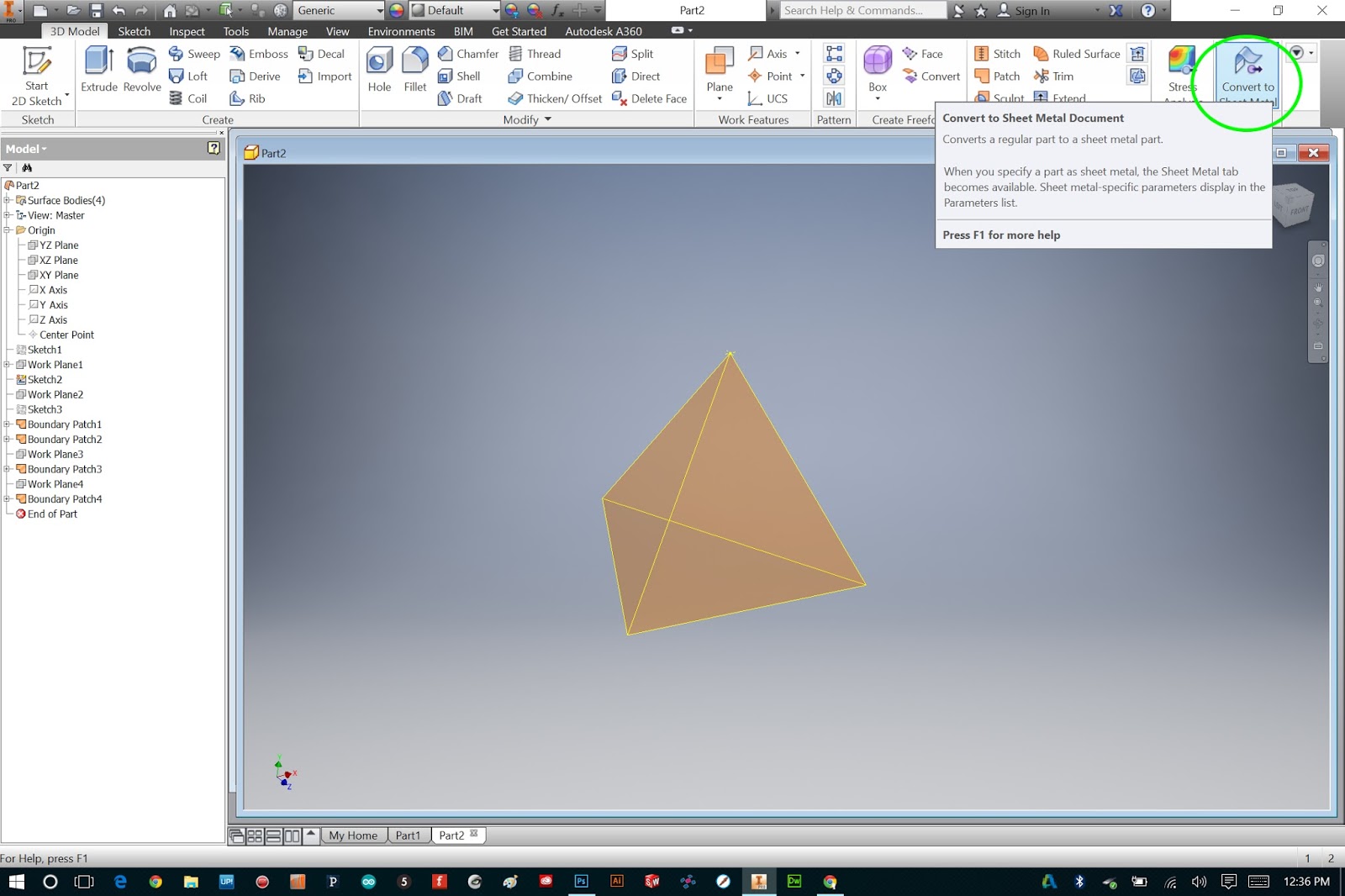
Now it is time to begin the sheet metal process. The first step is to click on "Convert to Sheet Metal" and set up the sheet metal rules.

I will be using .03" thick aluminum sheet when I build the physical version of this model, so I chose "Aluminum 6061" as my material. Then, click on the little pencil to define the sheet metal style and standards.

Inside the Style and Standards Editor, set the material thickness to .03". Inventor automatically assumes you want your "seams" to be equal to the material thickness, but I want them to be a bit tighter. So in the Miter/Rip/Seam Gap field, I replaced the "Thickness" variable with the value ".01 in".

Also, inventor assumes that you are just bending the aluminum without scoring it, so it calculates a realistic bend radius based on the material thickness. I replaced this value with ".01 in" as well.... I will be scoring my aluminum and will be able to achieve tighter bends.
These are the only fields I needed to edit: Thickness, Miter/Rip/Seam Gap, and Bend Radius. The rest I left as defined in the Aluminum 6061 profile.
You'll notice, when you close the dialog, that you now have a new set of features and tools. These are the sheet metal tools!
Now we are ready to start creating sheet metal faces, seams and bends. Unfortunately, we cannot define these using surfaces. So while it might seem redundant, our best option is to go back to each surface and new sketches right on top of them.

Fortunately, this process is quick and easy. You can right click on a surface and choose "new sketch"...

And the quickly use "Project Geometry" to grab lines right from the surfaces we already created.

It took me all of about 10 seconds to create sketches from each surface. Again, be sure that the loops in each sketch are complete and closed!

Once we have these sketches, we can hide the surfaces... we wont need those any more.
You might be annoyed with me right now.... thinking "Why would you create surfaces from sketches, only to then create sketches from the surfaces?"
The reason is because IF you were to use patterns to create some of your faces (I could have, but chose not to) you would need to do this step. You cannot pattern sketches in 3ed, but you can pattern surfaces.
Again, this is an approach that I thought was very straight forward and versatile... not necessarily the most efficient one. Anyway - let's continue.

Now that we have our "framework" of sketches, we are ready to create faces.
And Here is where I learned (the hard way) what NOT to do...

Inventor has a neat feature that allows you to, as you pick sketches to create faces from, specify which side is a bend (a.k.a. where it attaches to the rest of the model.)

That is, it WOULD be a nice feature, if it worked AT ALL. But most of the time, it will cause an annoying error...

Like the one above...

So instead of adding bend edges as we go, we are first going to create ALL of the faces as NEW solids...
And we will specify seams and bends later.

Also, here is where you can specify the offset of the sheet metal face.

Creating each face, one-by-one, using this method will usually result in overlapping geometry. That is fine... because next we are going to create clearence using the corner seam tool
It is important to create corner seams EVEN FOR THE CORNERS THAT WILL BE BENDS!
Why? I am not completely sure, but that it the only way I've gotten it to work.

To create corner seams, select the corner seam tool...

Then click the two edges that will have the seam added... in this case they are coincident, so just click on the "shared" edge twice.

Note that here is where you can specify how the two edges meet... either symmetric, or overlapping.

Add a corner seam for every edge (again, even for the ones that will eventually be bend edges).

Now, we are ready to ad our bends. To do this, select the "bend" tool...

And select the two edges you want the bend to happen between.

I added bends to the bottom three seams.

Once you have added your seams and bends, you should have a functioning Sheet Metal Part! The true test is to see if it will unfold properly...
To unfold, select the unfold feature...

First, select a stationary face.

Then, click on "add all bends".
If you see a preview of the faces unfolded, congratulations! Your sheet metal part works properly!
If not, you need to revise yours seam gaps and bends. When in doubt, check what error message you are getting, and then ask the google!

When you unfold it, you can see what your part would look like flattened. This is quite special, because from this we can create a pattern, and actually cut, score and fold some real life metal!

You can also partially fold and unfold the model, by selecting bends manually.

Whew! Finally, we have a sheet metal part. A simulation of sheet metal, folded!
- - - - - - - - - - - - - - - - - - - -
There are more blog posts on this topic coming soon, including:
1.) adding fasterners/hardware to the sheet metal model
2.) creating an assembly of sheet metal parts
- and, of course -
3.) making an ACTUAL sheet metal object, directly from the template generated in Inventor!
Thanks for reading... check back soon!!
**update... read Part Two, here!!
No comments:
Post a Comment