Monday, October 26, 2015

Autodesk Inventor: Sheet Metal Design Check (In paper!)


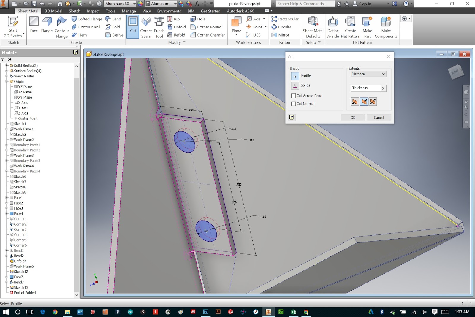
For my sheet metal project in Autodesk Inventor, I last left off at adding tabs and holes for fasterners, then unfolding the model flat.  The next step, if you are going to actually use this patten to make something (which I am...) is to output the template to a printer.


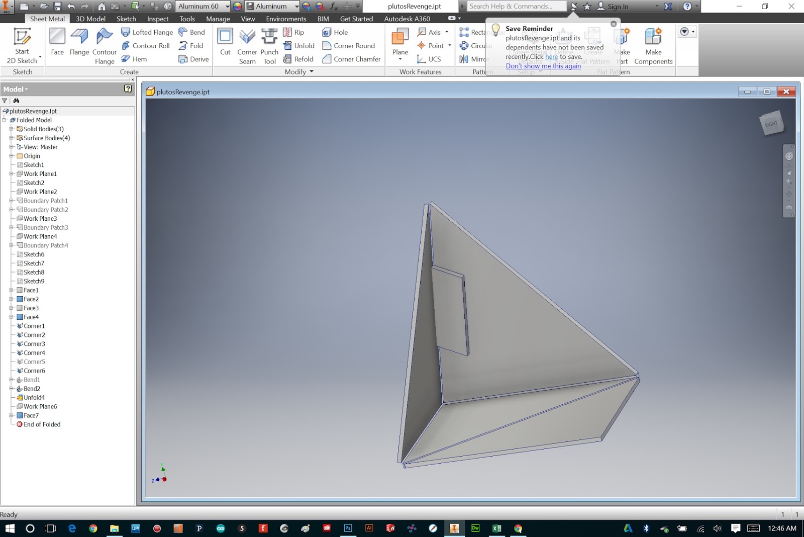
First, select from the sheet metal features tab "Create Flat Pattern."


After Inventor thinks on it for a second, you should see something like what is pictured above.


Next, right click on "Flat Pattern" in your feature tree, and select "Save Copy As..."


Name your file something memorable, and be sure to select DWG as your "type".  Then click save.


In the next dialog, just be sure to select for file version "AutoCad 2004 Drawing" (this version will be best compatible with other vector editing platforms in case we'll ever need to edit elsewhere in the future.)  Then click OK.


Next, minimize Inventor and browse to where you saved your DWG file.  Right click the file and choose "Open With..."


And select "AutoCad DWG Launcher".  This will open the file in Inventor under the DWG view mode.


From here, select the Print button.


Select your printer, and set the scale to be "Model 1:1" (this will ensure you are printing to the correct scale of the model).  Then press OK.


Here is my sheet metal template printed on standard legal paper... next to the original paper prototype!

Before going ahead and transfering this template to sheet metal, I like to first do a design check in paper/cardboard:


Spray-mounted onto .06" craft board.


Cut and scored.  I used a center punch to punch holes in the tabs (and realized after that I forgot to add the adjacent holes in my model... this is why I do a design check!!)

I ended up adding these by hand.


It is important NOT to glue this model together, because it will be useful to be able to fold and unfold it and use as a reference as I build the aluminum version.


And just for fun, I decided to build my slightly more complex model in cardboard:


For a more detailed run through of cutting, scoring and folding a paper model, see my blog post on that very topic here.

Next up: The final build (in aluminum)...

Sunday, October 25, 2015

Visiting Northwestern


Last week I visited the Segal Institute of Design at Northwestern University to give a talk for a class called "Designing Product Interactions."  This course is part of the "Engineering Design and Innovation" program at NU.


To the left of my is Craig Sampson - one of the instructors of the course.  He has been involved in design, engineering, and innovation for many years, much of it as a leader at IDEO. Now he has his own independent consulting business. For much of this time he has had some relationship with Northwestern University, and in recent years the Segal Design Institute at NU has been gaining prominence, and he has gotten more involved - specifically with the graduate program Engineering Design & Innovation.

Craig Sampson is a really kind and thoughtful guy.  I really love his interpretation of my work - it has made me think quite a bit about why I do what I do, and how I can do it even better.  I also really enjoy how he runs his class - I would have loved to be in a course like this and if I ever return to school to seek another degree I would highly consider applying to this one!


To the right of me (above) is Craig Shultz, a PHD student studying Haptic Technology (I'll get back to this in a moment.)  Talking with him for just a few hours, it struck me that while he is quite tech-oriented and is clearly a genius, he has a very human, very creative and artistic side to his personality and practice. I was intrigued that while he is doing some hard research and science at the University, he still finds it crucial to maintain a creative and experimental approach to his work.


After my talk, I held a short Q&A while I showed some of my prototypes to the grad students, and let them play and explore.


Several students tried out a portable version of Pung - I was quite pleased to see that even engineers totally let loose while competitively screaming at their paddles!


After class, Shultz (I'm going to call him that since both of my hosts were named Craig) brought me to see the work he's doing in the Haptic Technology lab.  As I approached his work space, I couldn't help but notice a turntable chilling next to an oscilloscope. now I was curious...


The first thing Schultz showed me totally blew my mind.  Pictured above is a prototype (a really well-made one, too!) of a haptic touch display for a smart phone.  No, I am not talking about a vibration motor or a "rumble pad."  This is way more magical than that...

Basically, Schultz is using ultra-sonic waves, which cause the frictional glass surface to resonate or oscillate on a very small scale.  As the surface moves up and down, it creates a tiny "buffer" of air between the glass and your finger.  This acts almost as a lubricant - and essentially allows electronic control of the surface friction in real time.

What does this mean?  Well, the photo above shows an app that displays five different textures.  As I swiped my finger accross each strip, I could FEEL the different textures.  It was insane... expecially the third from the top, which literally felt like sandpaper!  But, it was a flat glass screen.  Incredible.


The next project he showed me was a similar princeple, but here instead of "lubricating" a frictional surface with ultrasonic waves, he is creating electrical fields across a surface that actually attract your finger to it.  So, still using electricity to alter the friction of a surface, but sort of the opposite strategy.

Here, voltage can lead to a dramatic increase of friction coefficient. When the external voltage is turned on and off periodically, the friction coefficient goes up and down almost synchronously.

Here, he is using anodized aluminum because it is conductive, but the surface is very resistive.


First, Shultz played a sine wave through the surface.  As you drag your finger across, you can feel (and even see) the surface periodically "gripping" your finger.  But the next part was the most magical...

Shultz noticed, at some point, that as he moved his finger around on the surface, he could hear hints of the sine wave he was playing.  Curious, he tinkered with the software and the amplifier, and played some music through the surface...


The result is truly magical.  As you move your finger accross, the change in friction in synchronous with the beat of the music. You can FEEL the music in your finger tip...

Even more amazing - you can hear it!  But the sound isn't coming from a speaker, or from the surface.  The sound actually originates from the electric field between your skin and the surface.  In order words - the surface turns your finger tips into tiny speakers!!


The next phase of Craig Shultz' research, along with some other phd students, is to create a motion system where the "attractive" surface can actually guide your fingers around on the screen - like a technological Ouija board.  I am thrilled by this research and cannot wait to see more.  I told Craig that if he ever needs a creative collaborator, I would jump all over the opportunity!

Wall of Weird - "Trading Card Board"


For the "Common Read" Program at Cardinal Stritch, I was asked to help create some accessible programming to go along with this year's book - Gris Grimly's graphic-novel adaptation of Frankenstein.

After some brainstorming, we decided on a fun low-tech activity for people on campus to partake in: The Wall of Weird.  Frankenstein's monster is basically a weirdo - an outcast.  So we are asking passers-by to create a "weird trading card" to contribute to our Wall of Weird.

My job was to create the template - and we decided it would be fun to create a giant board for people to stand behind and have their Polaroid photo taken... à la how people made fake IDs in the 70s?

Warning!  This build is quick and dirty.  I had very little time to complete this, so I rushed through and knocked it out in one evening.


So participants can write in their info onto the template, I selected some white-board finish Masonite as the material for the board.  I have used this before to create some low-budget dry-erase boards in the Atelier (my fabrication lab).


After drawing a rough window (with a dry-erase marker!) I drilled corner holes with a spade bit.


I then scribed adjacent lines with an x-acto knife. These will serve as cutting guides, but ensure that if the dry erase paint chips curing cutting, it will not interrupt this line.


I cut each line with a jigsaw - very carefully so I would not have to revisit with sandpaper.


I decided I wanted to add handles to this thing so participants could easily hold it in front of themselves while having their photo taken.  To avoid have any exposed bolts on the face of the board, I cut some small plates from the window scrap.  I will instead mount the handles to these, and epoxy them onto the back of the board.


Drilled and countersunk to accomodate 8-32 bolts.


I then used two-part epoxy to adhere these to the board.  Using binder clips and a brass weight in lieu of clamps.


Based on the window I cut, I (quickly) drew up the graphics for the board in Adobe Illustrator.  I based these roughly on the cover of the book, and this font artwork inspired by the graphic novel.


Rather than printing out huge vinyls (I am using a 12" cutter so that's not always possible) I am creating the borders by cutting the corners on the plotter, then connecting them with black electrical tape (which is essentially just matte black vinyl anyway.)


A close-up of the vinyl corners meeting the electrical tape sides.


Not perfect, but it will look great in photos.


For the rest of the decals, I cut, weeded and transferred each vinyl.


The finished board.


How the board will be used.  I am definitely going to write something better when I actually participate... to be honest I dream about cats more than robots...


Though this was rushed and there are many flaws and imperfections, I am happy with this for being a one-evening build.

The last thing to do for this is to create a backdrop - I am planning on blowing up a background from a frame in the novel, and printing it on the architecture plotter at Kinkos.  I'll most likely post the final images on my Instagram.


**Update: I stopped by Kinko's today to run a backdrop from the Architecture plotter there.  It's about $10 for a 3 ft x 5 ft print... not the best quality but well worth the price for a quick large grey scale print!


Here's a snapshot, with my feet for scale reference!

This backdrop was created from the background in a frame in Gris Grimly's novel.


Monday, October 19, 2015

Autodesk Inventor: Sheet Metal Tabs and Fasteners


After creating a sheet metal cad model in Autodesk Inventor (as I outlined in Part One) I wanted to add tabs and holes for fasterners, so when I build this thing with real materials it will be sturdy and will stay together without any tape or glue or anything like that.

Below I have outlined my process for adding tabs and holes for fasteners (m3 bolts in this case).


First, it is going to be helpful to unfold one side of my vessel so I can easily see inside as I draw the tabs.


I selected the bottom face as my stationary reference, and picked one of the edges to unfold.


Next, I have to create an offset plane to create a sketch for my first tab.  I don't want to sketch directly on the face the tab will meet with, because Autodesk doesn't like it when two faces exist in the exact same location (and the real world doesn't exactly allow for this either!)


So I just create a plane offset .01 inches from the inside face.


Next, I sketch my tab.  Because I'm drawing from an angle, it is important to make use of constraints and dimensions to make sure everything lines up correctly.  From this awkward perspective, I can't rely on eye-balling any geometry.

In addition, I dimensioned my "holes" to be 3mm in diameter, since this is the diameter of the fasteners I'll be using when I build this vessel.


After sketching my tab, I create a "face" feature from it, and select "new solid".


The resulting face, pictured above.


Next, I select the two adjacent edges to create a bend for the new face.


Since the holes I drew were only reference geometry (or construction lines as I usually call them) I am going to select that sketch and share it, so I can easily reference it again.


I sometimes find it helpful to change the visual style to "Shaded with Hidden Edges" so I can see behind obstructions.


Now it is time to add holes for fasteners.  I create a new sketch on the face of the tab I created...


 And re-draw my 3 mm holes, referencing the original sketch I drew.


 I then create a "cut" feature from that sketch...


 And select "All" for extents, making sure the cutting direction is correct.


To make sure it cuts through the tab AND the surface the tab will fasten to, I select "Solid" and then click on the adjacent surface...


Resulting in holes that go through the tab, and the side of the vessel.  This will allow me, when I build this thing in sheet aluminum, to fasten it together with bolts.


I repeat this whole process for all three faces.  Tab, holes, tab holes.  Yay!  Fun!


And in the end. unfold the vessel.  My sheet metal template is complete!

Soon I will be actually fabricating this thing... check out the next step here.